Hairstyle Modeling
Alpha-Step
Beta-Step
Gamma-Step
The method of hairstyle that we will be discussing consists of three steps. The first step
is the Alpha-step. This step defines and ellipsoidal hull of the head model. This hull is used as an
approximation to the head. Pores are then specified onto this approximated ellipsoidal hull. The Beta-step
consists of calculating the bending of the hair. This bending is based on a cantillever beam.
This step also incorporates collision detection with the head model. The Gamma-step is the final step and consists
of cutting the hair and modifying it to the desired shape.
Alpha-Step (Ellipsoidal Approximation
An ellipsiod representation of the head model is used for convenience. It is much easier to
specify the locations of pore positions on an ellipsoid than it is on a regular head model. A polar coordinate system
is available for an ellipsoid, which makes it easier to specify the locations. A regular polygonal representation
does not have an easy method of specifying locations. An ellipsoid also has the benefit of allowing
collision detection at a low computational cost.
Beta-Step (Calculate Hair Bending)
To understand how to calculate the bending of an individual hair we must first look at it in two
dimensions. We are going to use a cantilever beam representation for the hair. We assume that the
cantiliever beam is in an inital state where one end is fixed, as can be seen in the picture below.
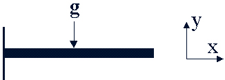
The beam is then loaded by the external force g, which is uniformly distributed on the whole beam. This
force allows type types of deformation to occur. These deformations are caused by bending moement and
by shearing force. Shearing force does not affect our calculations so to simplify things we will leave
it out. The x-axis is along the initial beam direction, and the y-axis is vertical to the direction of
the applied force. The y-axis represents the deflection direction of the beam.
The deformation process is governed by the following equation:
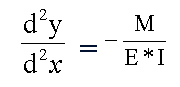
E is Young's modulas and I denotes the second moment of ares. E*I is the flexural regidity of the beam.
This value depends on the material of which the beam is composed. In theory this equation does not work
with large deformations.
The next step is to separate the beam into a finite number of linear segments. The distributed load g is
approximated by the sum of segmentally aveaged loads, as is seen in the image below.
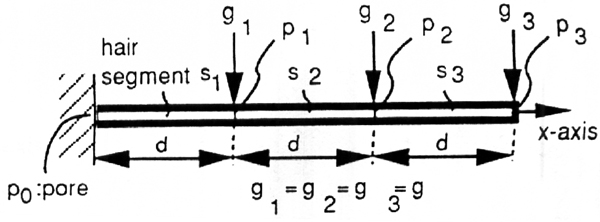
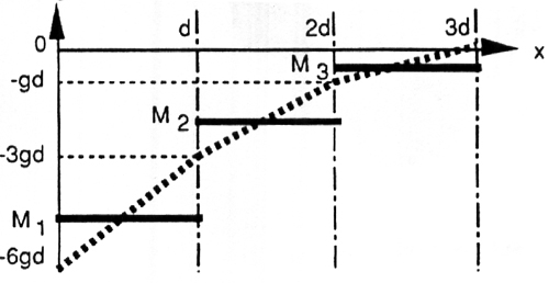
The average bending moment on a segment is approximated by
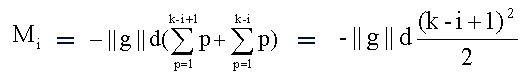
with the displacement y_i = (-1/2) * (M_i/E*I) * d^2
With these formulas we are able to come up with the following bending moment diagram:
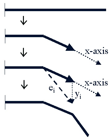
The bending of the beam is a rather simple process. The first step is to set the x-axis along the last segment
that has already been bent on the beam. The second step is to calculate the displacement of the beam in the y
direction at that point. This vector y_i is then added to the last beam segment that was bent. This creates a
new vector e_i. This vector is then moved to the endpoint of the bent beam and shortened to the length of the
beam segments. When this process is done to all of the beam segments, starting with the base of the beam, the
result is a realistically bent beam. This process can be seen in the picture below.
Now that we can bend the cantilever beam in two dimensions we must now use that knowledge and apply it into the
third dimension.
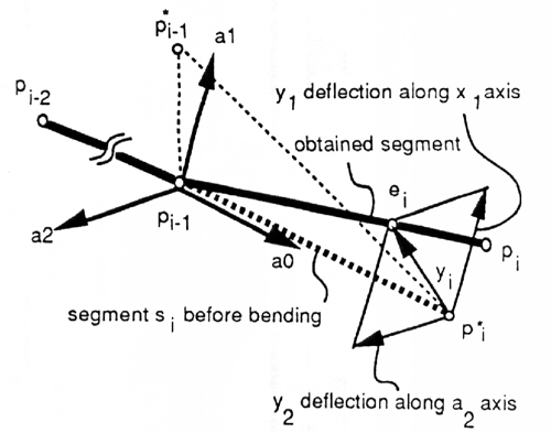
To do this, we must create a new coordinate system. The a_0 axis corresponds to the x-axis that is described in the
two dimensional case. The a_0 axis is defined as being along the the segment vector p_i-2 -> p_i-2. Next a point
p*_i is placed a certain distance along the a_0-axis. Finally a point p*_i-1 is a point that is displaced from
p_i-1. These three points now span a plane. The a_1-axis is vertical to the a_0-axis on the plane spanned by these
three points. The a_2-axis is orthogonal to both axis. Once we have this coordinate system set up we can then apply the
two dimensional method to obtain the deflections y_1 long the a_1-axis and y_2 along the a_2-axis. These deflections are
obtained by using the respective component of the force. The desired deflection of the vector y_i is obtained as y_1a_1 + y_2a_2.
The Beta-Step also involves collision detection. We are now talking about collision detection between the hair and the head model and not
between the individual hairs. Even with this simplification, the task of collision detection is still a large and complex process.
This is largely due to there being 400,000 individual hair segments and about 10,000 polygons making up the head. To calculate the
collisions between a large amount of hair segments and polygons would require a high computational cost. If we use an ellipsoidal
approximation the number of calculations is greatly reduced. You simply check the signature of E(p_i), where p_i is a node on the
cantilever beam. If a point is intersecting the ellipsoid that point is simply moved to the outside of the ellipsoid.
Gamma-Step (Hair Styling)
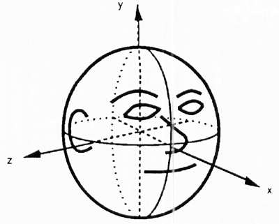
To give a brief demonstration of our hairstyling method we will go through how to create a bobbed hairstyle. The above image
demonstrates the head position in the local coordinate system that we will be using throughout this example.
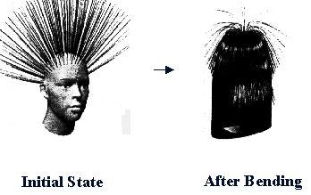
The first step in creating a hair style is to define the initial state. The initial state is when no force is being applied to
the hair. The second step is to add gravity to the model. These two steps create the above two images. The hair does not yet have
the look that we are seeking. The reason that the hair in the middle is standing straight up is that the force of gravity is being
applied in a parallel direction to the hair and in effect not causing any bending effects. The third step in the hairstyling process
is to cut the hair. This step is performed using polar coordinates of ellipsoid approximation and threshold. The range of hair pores are
specified. If the hair segments that fall into this range are below the given threshold. Meaning if the segment is below a certain
length, then it will not be displayed, an in effect cutting the segment off.
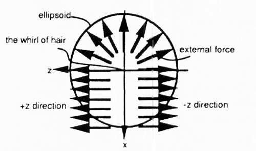
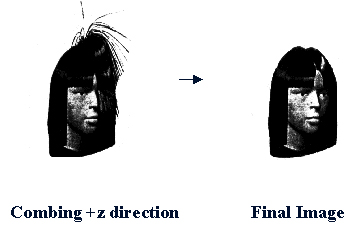
The last step in creating a bobbed hairstyle is to comb the hair. This is done by applying external forces to the hair in addition
to gravity. The external forces used to create bobbed hair are shown above. The forces are first applied in the positive z direction
and then in the opposite. The result of the cutting and combing is shown above. As you can see the result is very satisfactory. The hairstyle
that we recreated is very realistic which accomplishes its task.
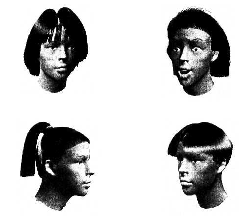
Shown above are some other examples of using this hairstyling method. The image in the upper left hand corner was created by using
a similar method to the bobbed hairstyle. The hairstyle in the upper right was created by applying and external force in the negative x
direction (backwards). The hairstyle in the bottom left of the image was created in two parts. First the hair on the head was created and
then the ponytail was individual designed. The final hairstyle was the most difficult of all. The number of hair segment not to be displayed was
determined by the height of the hair pore.